 +86 13313703791
 +86 13313703791
 seren@ymgkplc.com


Description
3. Product Introduction (Anti-Template)
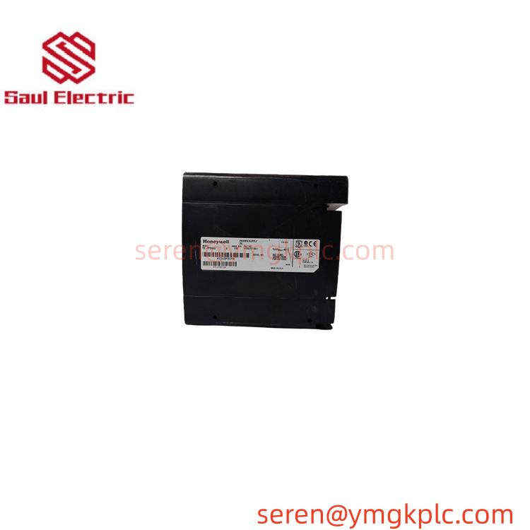
When a control chassis begins dropping modules or resetting without an obvious controller fault, the power budget deserves attention first. Honeywell TK-FPDXX2 is the coated, standard DC power supply for the Series-A chassis, accepting a 19.2–32 VDC input and distributing several regulated DC rails to the backplane.
The supply provides a maximum combined output of 70 W at 60°C. It is installed on the left side of the chassis and does not consume an I/O slot, making its capacity directly relevant to the total module load calculation.
4. Key Technical Specifications
| Parameter | Value |
|---|---|
| Manufacturer | Honeywell |
| Model | TK-FPDXX2 |
| Product Type | Standard DC Power Supply Module |
| System | Experion Series-A / Chassis Series-A |
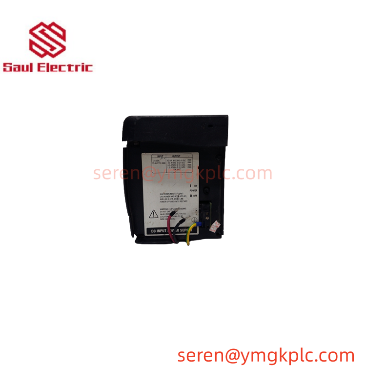
| Input Voltage | 19.2–32 VDC |
| Input Power | 100 W |
| Maximum Inrush Current | 30 A |
| Maximum Total Output | 70 W at 60°C |
| Backplane Output | 1.2 VDC / 3.3 VDC / 5.1 VDC / 24 VDC |
| Maximum 1.2 V Output | 1.5 A |
| Maximum 3.3 V Output | 4 A |
| Maximum 5.1 V Output | 10 A |
| Maximum 24 V Output | 2.8 A |
| Fuse | Non-replaceable soldered fuse |
| Wiring | #14 AWG (1.4 mm²) |
| Dimensions | Approx. 11.2 × 14.5 × 14.0 cm |
| Approx. Weight | 1.1 kg |
| Mounting Location | Left side of chassis; no I/O slot consumed |
The important number here is 70 W, not 100 W. The 100 W figure refers to input power, while the combined backplane output is limited to 70 W at 60°C. Honeywell’s technical data also states that the combined 5.1 V, 24 V, 3.3 V, and 1.2 V output must remain within this 70 W ceiling.
The DC input has some additional tolerance during motor-starting conditions: the documented specification permits the input to fall to 16 V for a maximum of two minutes per hour. That should not be interpreted as a normal operating input range.
5. Field Application & Technical Pitfalls (The Engineer’s Guide)
For maintenance engineers, TK-FPDXX2 is a chassis-level power component. A failure here can affect several downstream modules simultaneously, which makes diagnosis different from replacing a single failed I/O card.
- Experion Series-A control chassis
The module supplies the internal DC rails required by the chassis backplane and installed control/I/O modules. - Remote I/O and process-control installations
Where multiple modules share one chassis power supply, available power must be calculated from the actual module mix. A supply can appear healthy with a light load and become unstable after the full configuration is installed. - Legacy plant maintenance
TK-FPDXX2 is particularly useful as a replacement spare for established Series-A installations where maintaining the existing architecture is more economical than replacing an entire control chassis.
Three replacement pitfalls deserve attention:
- Input-voltage mismatch: TK-FPDXX2 is the DC-input version. Do not confuse it with TK-FPCXX2, which is the AC-input version. The documented input range for TK-FPDXX2 is 19.2–32 VDC.
- Power-budget error: Do not calculate available capacity from the 100 W input figure. The combined usable backplane output is limited to 70 W at 60°C.
- Inrush and fuse behavior: The documented maximum inrush current is 30 A, and the input protection uses a non-replaceable soldered fuse. Repeated power cycling or an external wiring fault should therefore be investigated rather than simply cycling the supply again.
Do not substitute a power supply based only on physical fit. The chassis expects specific backplane rails, and the total load has to stay within the supply’s thermal and electrical limits.
Lesson learned: A replacement supply may start normally during a bench test and still fail once the complete chassis is populated. In a typical field scenario, the engineer checks the supply voltage, sees 24 VDC present, and initially declares the unit healthy—only to discover that the total module load exceeds the 70 W output limit at operating temperature.
6. Quality Control (QC) SOP & Transparency
- Inbound Verification
- Verify the exact Honeywell model marking: TK-FPDXX2.
- Check the housing, connectors, mounting hardware, and identification labels.
- Confirm that the unit is the DC-input version rather than the visually similar AC-input variant.
- Inspect for corrosion, damaged terminals, cracked insulation, or evidence of previous electrical stress.
- Record the physical condition and packaging condition separately.
- Live Rig Testing
- Apply a controlled DC input within the specified 19.2–32 VDC range.
- Verify startup behavior and output stability.
- Test the power supply with a compatible Series-A chassis where available.
- Confirm the expected backplane rails under representative load.
- Monitor startup inrush behavior and check for abnormal shutdown or protection events.
- Parameter Testing
- Measure the 1.2 V, 3.3 V, 5.1 V, and 24 V backplane outputs.
- Check output voltage stability at low and representative loads.
- Verify total power delivery remains within the 70 W specification.
- Monitor temperature rise during sustained operation.
- Check for excessive ripple, unstable output, abnormal current consumption, or intermittent shutdown.
- Final QA & Packaging
- Record the exact model, serial information, and test results.
- Apply a QC-passed identification label after testing.
- Place the unit in protective packaging suitable for industrial electronic equipment.
- Protect the connectors and mounting surfaces from impact.
- Provide the applicable test record and a 12-month warranty under the agreed warranty terms.
7. Frequently Asked Questions (FAQ)
Q1. What is Honeywell TK-FPDXX2 used for?
It is a standard DC power supply module for the Series-A chassis, providing the internal DC rails needed by the installed control and I/O modules.
Q2. Is TK-FPDXX2 an AC or DC input power supply?
DC. Its documented input range is 19.2–32 VDC. The corresponding AC-input model is TK-FPCXX2.
Q3. How much power can TK-FPDXX2 actually provide?
The maximum combined backplane output is 70 W at 60°C. This is the number that should be used when calculating chassis capacity—not the 100 W input-power rating.
Q4. Where is the power supply installed?
It is mounted on the left side of the chassis and does not consume a normal I/O slot.
Q5. Can I hot-swap TK-FPDXX2?
Do not assume it is safe. Power-supply replacement procedures depend on the specific chassis configuration and whether redundant power architecture is installed. Unless the applicable maintenance procedure explicitly permits live replacement, isolate the chassis before removing the module.
Q6. What is the difference between TK-FPDXX2 and TK-FPCXX2?
The critical difference is the input source. TK-FPDXX2 accepts 19.2–32 VDC, while TK-FPCXX2 is designed for selectable AC input. They should not be treated as interchangeable merely because they perform the same general power-supply function.
Q7. What warranty is available?
A 12-month warranty can be provided under the agreed supply terms. For a replacement power supply, I would also recommend confirming the chassis model, installed module count, and existing input power arrangement before finalizing the spare.
Honeywell TC-CCR014 | C200 Redundant Network Interface Module
HONEYWELL 90088‑A‑9001 Industrial Control I/O Module
- WhatsApp: +86 13313703791
- Email: seren@ymgkplc.com
- Phone: +86 13313703791
- Wechat: +86 13313703791
- Website: www.xiongbaparts.com