 +86 18030182217
 +86 18030182217
 sandydcsplc@gmail.com


Description
Product Core Brief
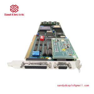
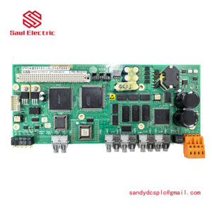
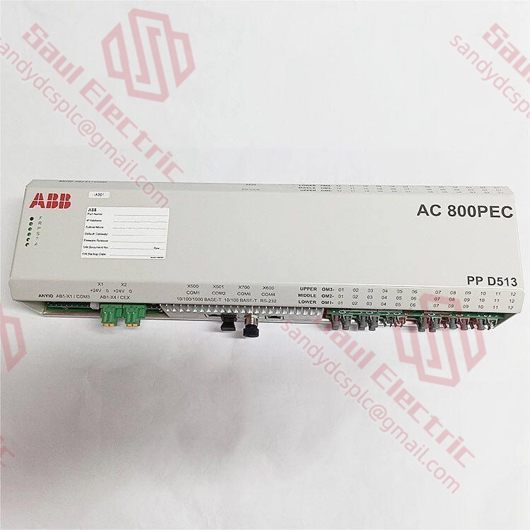
- Model: ABB PPD513A-23-111615 (3BHE series part number)
- Brand: ABB (Switzerland-Sweden)
- Series: UNITROL Excitation Control System Series
- Core Function: Automatic voltage regulator processor for synchronous generator excitation control. Condition: New Surplus, not refurbished.
- Type: Excitation Control Processor / AVR Module
- Key Specs: PID Voltage Regulation | Fieldbus Communication | Redundancy Capable
Key Technical Specifications
| Parameter Name | Specification Value |
|---|---|
| Model Number | PPD513A-23-111615 |
| Manufacturer | ABB |
| Product Category | Excitation Control Processor |
| Application | UNITROL Excitation Systems |
| Input Voltage | 24 V DC ±10% (subject to verification) |
| Control Function | Automatic Voltage Regulation (AVR) |
| Communication Protocol | Fieldbus / Ethernet / Serial (refer to manual) |
| Operating Temperature | -20°C to +60°C (typical industrial range) |
| Protection Rating | IP20 (panel mount enclosure) |
| Mounting Type | Rack Mount / DIN Rail |
| Processor Type | High-performance CPU for real-time control |
| Memory | Non-volatile storage for configuration |
| Weight | Approximately 1.8 kg |
| Warranty | 1 year (supplier dependent) |
⚠️ Note: Specific technical parameters require verification against the original ABB UNITROL technical manual. Contact technical support for confirmed datasheets and application notes.
Product Introduction
The ABB PPD513A-23-111615 is an excitation control processor designed for UNITROL automatic voltage regulator systems. This module manages field current regulation in synchronous generators and motors to maintain stable output voltage under varying load conditions. It is commonly deployed in power generation facilities, industrial plants, and marine power systems.As an upgraded iteration in ABB’s excitation control family, the PPD513A offers enhanced processing capability compared to earlier PPD512 models. Units available through surplus channels provide cost advantages over factory-direct procurement, where lead times can exceed 10-14 weeks. Engineers should verify firmware revision and system compatibility before installation to avoid commissioning delays.
Installation & Configuration Guide
Phase 1: Pre-Installation (10 mins)
⚠️ Safety First:
- Notify production teams of planned downtime.
- Verify generator is offline and isolated from grid.
- Disconnect power to excitation control system (including UPS backup).
- Wait 5 minutes for capacitor discharge in power circuits.
Tool Checklist:
- Anti-static wrist strap + mat
- Phillips screwdriver (PH1 size)
- Multimeter (Fluke 115 or equivalent)
- Label maker + marker
- Smartphone (for photographing settings)
Backup Procedures:
- Export running excitation parameters (save to USB + cloud storage).
- Photograph DIP switch/jumper positions (zoomed, clear shots).
- Photograph wiring terminals (every wire location and number).
- Photograph overall rack layout (prevents wrong slot installation).
Phase 2: Removal (15 mins)
Steps (Rack or DIN rail mount):
- Remove front cover (if applicable): Press sides gently to release snap fittings.
- Disconnect wiring:
- Record terminal numbers for every wire (tag each one).
- Loosen terminal screws counter-clockwise.
- Pull wires gently (do not yank; terminal blocks can crack).
- Release the module:
- Locate rail latch (typically at bottom edge).
- Use flathead screwdriver to push latch down.
- Pull module straight out (perpendicular to backplane).
- Inspect backplane connectors:
- Check for bent or corroded pins.
- Use compressed air if dusty (do NOT touch pins with bare hands).
⚠️ Crucial Notes:
- Configuration stickers may exist on old modules. Photograph before removal.
- Do not use excessive force; backplane pins bend easily and are costly to repair.
Phase 3: Installation (20 mins)
Steps:
- ESD Protection: Wear anti-static strap before removing module from bag.
- Model Verification: Confirm new model number matches old one exactly (including suffix).
- Configuration Replication (CRITICAL!):
- Using photographs, replicate DIP switch and jumper settings.
- Common settings:
- Node Address: DIP switches 1-8
- Baud Rate: 9600 / 19200 / 115200
- Termination Resistor: ON (bus end) / OFF (middle node)
- Insert into Rack:
- Align module with backplane connector (keyed slots; one-way insertion).
- Press firmly until “click” heard (latch engaged).
- Ensure module sits flush with adjacent units.
- Reconnect Wiring:
- Reinsert wires per tags/photographs.
- Tighten terminal screws clockwise (approx. 0.5 N·m torque).
- Gentle tug test on each wire.
Self-Checklist:
- DIP switches correctly set
- All cables connected securely
- Terminal screws tightened
- Module latches locked
- No loose tools in rack
Phase 4: Power-On & Testing (30 mins)
Pre-Power Checks:
- Double-check all wiring against photographs.
- Measure input voltage (should be 24 V DC ±10%).
- Check for short circuits (resistance between +24 V and GND; should be >10 kΩ).
Power-On Sequence:
- Power up control rack first (not entire plant/field devices).
- Observe Module LEDs:
- Solid Green (RUN) → Normal boot
- Flashing Red (ERR) → Refer to fault codes
- Flashing Yellow (DIAG) → Warning, but operational
- Connect Programming Software:
- Open ABB excitation configuration tool.
- Scan network; locate new module.
- Read module info; verify firmware version.
- Download Program:
- If identical model, download backup directly.
- If upgraded model, recompilation may be needed.
- Switch to RUN mode after download.
- Functional Testing:
- Force/toggle I/O points to check response.
- Verify communication status (HMI/SCADA connections).
- Simulate one complete excitation control loop.
Final Sign-off:
- System runs >30 minutes without alarms.
- All monitoring parameters stable.
- Log replacement info (date, technician name, new serial number).
⚠️ Troubleshooting:
- No Comm → Check IP address, cables, switch ports.
- Solid ERR Light → Firmware mismatch; attempt correct firmware flash.
- Can’t Download Program → Check programming cable and software version compatibility.
Quality Control & Inspection Process
Inbound Inspection
Traceability:
- Verify against original packing list and customs declarations.
- Cross-check serial numbers with ABB documentation.
Anti-Counterfeit:
- Serial number verification with manufacturer.
- Anti-counterfeit label inspection (holograms, security features).
Visual Inspection:
- No corrosion on terminals or connectors.
- No scratches on housing or PCB.
- No repair marks or reflow soldering evidence.
- No yellowing or aging on plastic components.
Accessories Check:
- Manuals included (if originally supplied).
- Factory certificates present.
- Original packaging materials intact.
Live Functional Testing
Test Environment:
- Dedicated test rack with ABB UNITROL simulation system.
- Calibrated power supply (24 V DC, 5 A minimum).
Test Contents:
- Power-on self-test (LED indicators, startup sequence).
- Communication test (Fieldbus/Ethernet handshakes).
- I/O test (full range simulation of input/output signals).
- Load test (continuous operation >24 hours, recording temperature rise).
Test Records:
- Generate formal Test Report with timestamp.
- We can provide test videos/photos for customer review.
Electrical Parameter Testing
- Insulation resistance test (500 V megohmmeter, >10 MΩ).
- Ground continuity test (resistance <0.1 Ω).
- Withstand voltage test (if applicable per specification).
Firmware/Program Verification
- Read and record firmware version from module.
- If multiple versions exist, note the specific version (e.g., V3.2.1).
- Configuration backup (photograph DIP switch/jumper settings).
Final QC & Packaging
- Inspector signature confirmation on Test Report.
- Anti-static bag sealing with humidity indicator.
- Bubble wrap + carton packaging (double-box for international).
- Attach QC Passed label with inspection date.
Transparency: All units pass the above tests to ensure proper functionality. We document each step and can share inspection records upon request.
Technical Pitfall Guide
1. Firmware Revision Mismatch
Issue: New module firmware is too new or old, causing communication errors with the existing UNITROL system.Avoidance:
- Record the old module’s firmware version before replacing (usually on label or read via software).
- Specify the acceptable firmware range when purchasing.
- If there is a mismatch, contact the supplier to flash or downgrade the firmware.
Real Case: I saw a project where an engineer swapped a PPD513 module, and the excitation system kept reporting “Communication Timeout.” It took two days to realize the firmware bumped from V2.8 to V3.1, causing a minor protocol shift. The generator sat offline while we sorted it out.
2. DIP Switch / Jumper Configuration Errors
Issue: Factory default settings don’t match site requirements (e.g., node address, baud rate, terminating resistor).Avoidance:
- Take a photo of the old module’s DIP switches/jumpers before swapping.
- Verify and replicate the configuration on the new module before powering up.
- Special note: Bus terminating resistors (120 Ω) must only be at the two ends of the bus.
Tone: This is a rookie mistake, but it happens all the time. Take a picture! Take a picture! Take a picture! Important things are worth repeating.
3. Terminal / Cable Incompatibility
Issue: Interfaces on new and old modules aren’t identical (pinout changes, different connector types).Avoidance:
- Check the Wiring Diagram in advance.
- Prepare adapter terminals or be ready to recrimp.
- Note shield grounding methods (single-ended vs. double-ended).
Warning: With some ABB excitation modules, even if the models look similar, the pinouts might differ. Always check the manual; don’t just guess.
4. Power Supply Spec Differences
Issue: The new module draws more power, and the existing supply capacity is insufficient.Avoidance:
- Calculate the total rack power consumption and leave a 20% margin.
- If nearing the limit, consider adding a supplementary power module.
Data: For example, a PPD513A processor draws about 10 W, but if you mount multiple I/O modules in the same rack, the total could hit 80 W, making a 24 V/2 A supply inadequate.
5. Electrostatic Discharge (ESD)
Issue: Module fried by static electricity due to lack of ESD precautions.Avoidance:
- Wear an anti-static wrist strap.
- Work on an anti-static mat.
- Be especially careful in dry winter conditions.
Scare Tactic: I watched an engineer touch a module without a strap. The moment it powered on, it smoked. That was $3,500 down the drain.Keep these points in mind, and you’ll save yourself 90% of potential rework time.
Frequently Asked Questions (FAQ)
Q1: Is the ABB PPD513A-23-111615 still in production?A: The PPD513A series is considered a legacy product within ABB’s UNITROL lineup. ABB has released newer processor variants for their latest excitation systems, but factory-new PPD513A units have extended lead times (10-14 weeks typically). The surplus market offers available stock, but buyers should verify authenticity. We’ve seen refurbished units sold as “new” — always request factory packing slips and serial number verification before purchase.Q2: Can I hot-swap this module without shutting down the generator?A: No, hot-swapping is not supported on the PPD513A. This is a core excitation control processor tied directly to generator voltage regulation. Forcing a hot-swap risks:
- Backplane connector damage from inrush current.
- Loss of excitation control during swap (potential generator trip or grid instability).
- Voltage spikes affecting downstream equipment.
If your operation requires zero downtime, consider a redundant excitation processor setup. The upfront cost is higher, but critical for continuous-power facilities like hospitals or data centers.Q3: Will I lose my excitation parameters when replacing the PPD513A?A: Parameter storage depends on your system architecture:
- Scenario 1: Non-Volatile Memory or CF Card — Parameters load automatically after swap.
- Scenario 2: Network-Stored Configuration — Download from engineering workstation required.
- Scenario 3: No Backup — Worst case; parameters must be recreated manually.
My recommendation: Always export the running excitation parameters before hardware replacement. I’ve seen plants lose 36 hours of commissioning time because nobody backed up the AVR settings. Take the 10 minutes to save the file.Q4: What’s the difference between PPD512, PPD513, and PPD513A?A: These models represent different performance tiers within ABB’s excitation control family:表格
| Model | Performance Tier | Processing Capability | Redundancy Support |
|---|---|---|---|
| PPD512 | Standard | Basic AVR functions | Limited |
| PPD513 | Enhanced | Expanded I/O handling | Supported |
| PPD513A | High-End | Advanced algorithms | Full |
Direct interchangeability is not guaranteed. Even if physical form factors match, firmware and I/O mapping may differ. Always consult the ABB compatibility matrix before substituting models. In my experience, sticking with the exact model number avoids 90% of commissioning headaches.Q5: How do I verify this isn’t a refurbished unit sold as new?A: Several checks help identify refurbished vs. genuine new surplus:
- Packaging: Factory-sealed anti-static bags with ABB labels intact.
- Serial Number: Verify with ABB directly (they can confirm manufacture date).
- Physical Inspection: No screw marks, no yellowing on connectors, no corrosion.
- Documentation: Original packing list, warranty card, factory certificate should accompany.
- Firmware Date: Read firmware version; if it predates the supposed manufacture date, red flag.
We provide test videos and photos for customer review before shipment. If a supplier won’t share this, walk away.Q6: What firmware version should I look for?A: Firmware version requirements depend on your existing UNITROL system configuration. Before ordering:
- Read the old module’s firmware version (label or via software).
- Specify acceptable firmware range when purchasing.
- If mismatch occurs, supplier may need to flash or downgrade firmware.
Real case: I saw a project where an engineer swapped a module, and the excitation system kept reporting “Communication Timeout.” Took two days to realize firmware bumped from V2.8 to V3.1, causing a minor protocol shift. Record the version before you start.Q7: What is the warranty and return policy?A: Warranty Coverage:
- Inherent hardware faults (non-human damage).
- Functional anomalies from factory defects.
Not Covered:
- Human-caused damage (drops, water, ESD).
- Operation outside specifications (overvoltage, extreme temps).
- Force majeure (lightning, power surges).
After-Sales Process:
- Contact supplier with fault description (photos/videos ideal).
- Remote diagnostic assistance provided.
- If hardware failure confirmed:
- Within 7 days: Return/exchange.
- Within 1 year: Free replacement.
- After 1 year: Paid repair or discounted replacement.
Q8: What common mistakes should I avoid during installation?A: Five pitfalls I’ve seen repeatedly:
- DIP Switch Errors: Factory defaults rarely match site requirements. Photograph the old module before removal. I tell junior engineers: “Take a picture! Take a picture! Take a picture!”
- Termination Resistor Misconfiguration: 120 Ω resistors belong only at bus ends. Middle nodes must have termination OFF.
- Power Supply Undersizing: Calculate total rack consumption with 20% margin. An excitation system drawing extra current can trip the whole rack.
- ESD Damage: I watched an engineer touch a module without a wrist strap. Powered on — it smoked. That was $3,500 gone. Wear the strap, especially in dry conditions.
- Pinout Assumptions: Some ABB modules look identical but have different terminal assignments. Check the wiring diagram; don’t guess.
Keep these points in mind, and you’ll save yourself 90% of potential rework time.
- WhatsApp: +86 18030182217
- Email: sandydcsplc@gmail.com
- Phone: +86 18030182217
- Wechat: +86 18030182217
- Website: www.xiongbaparts.com